Isolating one FM channel in the FPGA
A worked example of putting DSP into the AD9361 datapath: the board delivers
one 200 kHz WBFM (wideband FM broadcast) channel, every other station removed
in the fabric before a sample leaves the board. It is the opt-in patch
firmware/patches/optional/0003-wbfm-channelizer.patch; read this to build it,
or as a template for your own FPGA filter.
Building it
The commands, and the check before flashing: build the FM channelizer example.
| default station | 102.1 MHz (Studio Brussel); the station is a runtime setting (retuning) |
| why delete the project first | the coefficients and the block-design change both need the FIR IP regenerated, and build_hdl.tcl reuses an existing pluto.xpr: without it the build silently produces the old filter |
| why it is opt-in | it narrows RX channel 0 to one broadcast channel |
| expected after the build | 96 / 220 DSP48s in utilization.rpt, and timing met |
Running it
The four iio_attr commands and the A/B check:
build the FM channelizer example.
The second rate, 528000 on cf-ad9361-lpc, engages the filter: it drives
GP_CONTROL bit 0, which selects the filtered path through the bypass mux.
Retuning to another station
The filter sits at DC and follows the LO, so any FM station works at runtime as long as the sample rate stays 4.224 MSPS:
# LO for a given station, in Hz
LO = station - 1056000
The flowgraph's Station (Hz) slider does this. A different sample rate needs
a rebuild: pick Fs = 384000 x k, set FS_IN in gen_fir_coe.py, regenerate
and rebuild.
Why the channel is shifted to DC first
Tuning on-channel puts the radio's own defects in the audio: a zero-IF receiver like the AD9361 (it mixes the tuned frequency straight to 0 Hz) leaks its local oscillator and carries a DC offset, both at exactly 0 Hz. So tune off-channel. But a FIR with real coefficients is symmetric about DC: asked to pass 1.0–1.2 MHz it passes −1.2 to −1.0 MHz too, a different station. Complex coefficients would cost four real filters instead of two.
Instead, shift the channel to DC, then lowpass. With the offset at exactly
Fs/4, multiplying by exp(-j*pi*n/2) cycles through 1, -j, -1, +j, which is
only swaps and sign flips: two registers and a 2-bit counter, no multipliers, no
NCO (numerically controlled oscillator), no block RAM.
| n | multiply by | (I, Q) becomes |
|---|---|---|
| 0 | 1 | ( I, Q) |
| 1 | −j | ( Q, −I) |
| 2 | −1 | (−I, −Q) |
| 3 | +j | (−Q, I) |
The rate plan
The offset must be Fs/4, and Fs/8 (after the ÷8 decimator) should be a whole
multiple of 48 kHz so audio needs no resampler: Fs = 384000 x k. For an offset
near 1 MHz, k = 11:
| Station | 102.1 MHz |
| AD9361 sample rate | 4.224 MSPS (= 384000 × 11) |
| Offset = Fs/4 | 1.056 MHz |
| RX LO | 101.044 MHz (= 102.1 − 1.056) |
| FPGA decimation | ÷8 |
| Delivered rate | 528 kSPS, channel centred at DC |
| Audio decimation | 528000 / 48000 = 11, exact |
2.083 MSPS (the AD9361's floor, Nyquist ±1.042 MHz) and 2.304 MSPS are too slow: the channel's upper edge needs 1.2 MHz.
The filter is what keeps the LO spur out. After the shift the spur sits at
−1.056 MHz = 2 × 528 kHz, so decimation folds it exactly onto DC, the centre
of the channel. The FIR's stopband there (about −84 dB; −78.5 dB worst case) is
what suppresses it. gen_fir_coe.py prints that frequency's response; re-check
it if you change the rate plan.
The datapath
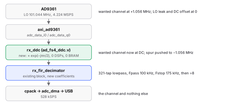
TX is unchanged. Channel 1 is not a usable second receiver with this build.
The patch pins rx_filt_chan to 2 regardless of patch 0021 (its coefficients
are one FM channel, so RX2 through them would give the same station twice), and
cpack clocks every channel on channel 0's strobe, so channel 1 gets a 1-in-8
downsample with no anti-aliasing: ±264 kHz usable, with roughly ±2 MHz folded on
top. See both-receive-channels.md.
| File | What it does |
|---|---|
firmware/src/hdl/projects/pluto/ad_fs4_ddc.v |
the Fs/4 shifter |
firmware/src/hdl/projects/pluto/system_bd.tcl |
wires it in, repoints the coefficients |
firmware/patches/optional/0003-wbfm-channelizer.patch |
both of the above; opt-in, setup.sh does not apply it |
firmware/scripts/gen_fir_coe.py |
designs and verifies the coefficients (no MATLAB needed) |
firmware/scripts/coefile_wbfm_102100.coe |
its output, 321 taps |
docs/grc/fishball_wbfm_rx.grc |
the GNU Radio receiver, with no software channel filter |
Filter performance and cost
321 taps, Kaiser window, quantised to 16-bit integers summing to 2^17 (the stock DC-gain convention):
| Passband ripple, 0–100 kHz | 0.0019 dB |
| Stopband edge, 175 kHz | −113 dB |
| Adjacent channel carrier, 200 kHz | −78.7 dB |
| Worst case anywhere ≥ 175 kHz | −78.5 dB |
| Before | After | |
|---|---|---|
| DSP48s | 72 | 96 / 220 (43.6%) |
| Slice LUTs | 11 893 | 12 664 / 53 200 (23.8%) |
| Slice registers | 20 851 | 22 300 / 106 400 (21.0%) |
| Worst negative slack | — | +0.292 ns, 0 failing endpoints of 55 269 |
The shifter costs no DSPs; the +24 is the filter going from 129 to 321 taps. Taps are cheap because a ÷8 filter has eight input periods per output. More than ~321 taps does not help: the filter is then limited by 16-bit coefficient quantisation.
Designing your own filter
# run from: firmware/scripts
python3 gen_fir_coe.py          # stdlib only: no venv needed
Standard library only. It prints the response at the passband edge, stopband
edge, adjacent-channel carrier and folded LO spur, checks ripple and worst-case
stopband, and exits non-zero rather than writing a file that fails. Edit the
configuration block at the top to retarget it. gen_fir_coe.m is the MATLAB
equivalent (equiripple, ~30% fewer taps, needs the Signal Processing Toolbox).