Write a pin pattern in Python
A complete program that puts a clock, a frame pulse and a sync marker on the four JP5 pins, with the transmitter muted.
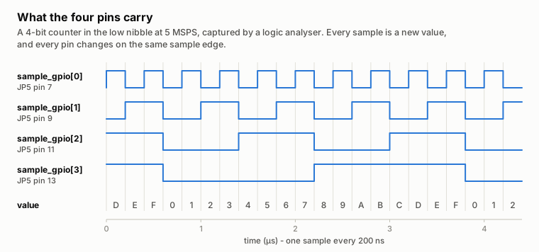
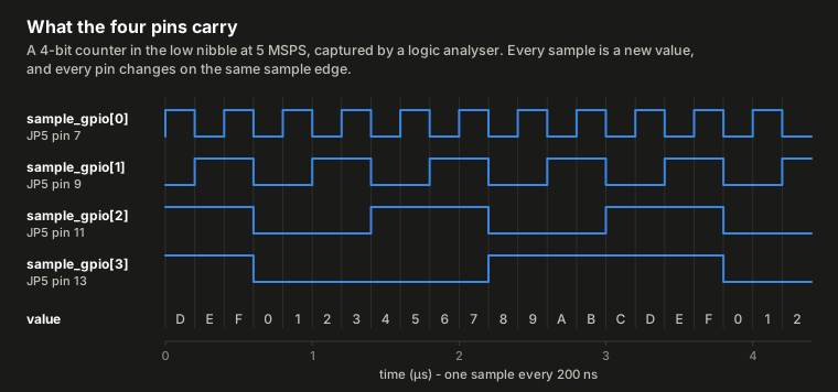
What a pattern looks like on the pins: here a counter, measured with a logic analyser.
Mute after the buffer starts, and read it back
Opening a TX buffer can itself raise the attenuator. The program mutes in
step 6, after tx(), and checks the result. Before raising any output, read
before you transmit.
There is no "clock mode" register: the pattern is data. A pin is a clock because its bit alternates. OR the nibble in last, after every scaling, gain or format conversion, or those steps overwrite it. A complete program:
# run from: your host (not the board), in a venv: .venv/bin/pip install pyadi-iio numpy; .venv/bin/python example.py
import adi, iio, numpy as np

URI = "ip:192.168.2.1"
N   = 4096                     # buffer length in samples

# 1. Turn the bit-map on. It is an attribute of the DAC core rather than of
#    the radio, so pyadi-iio does not expose it - reach it through libiio.
dac = iio.Context(URI).find_device("cf-ad9361-dds-core-lpc")
dac.attrs["tx_sample_gpio_en"].value = "1"

# 2. The radio. The transmitter is muted AFTER the buffer starts (step 6):
#    starting a buffer restores a cached attenuation, so a mute written here
#    would be overwritten. Muted, the pins still work: the nibble never
#    reaches the DAC.
sdr = adi.ad9361(uri=URI)
sdr.tx_enabled_channels = [0]
sdr.sample_rate = int(30.72e6)
sdr.tx_lo = int(2.4e9)
sdr.tx_cyclic_buffer = True    # repeat the buffer forever -> a steady clock
fs = sdr.sample_rate

# 3. The RF you actually want to transmit, as int16.
n   = np.arange(N)
sig = 0.5 * 2**15 * np.exp(2j * np.pi * 1e6 * n / fs)
i16 = sig.real.astype(np.int16)
q16 = sig.imag.astype(np.int16)

# 4. The digital side-channel: one bit per pin, as a function of sample index.
bit0 = (n % 2  == 0)                   # master clock: square wave at fs/2
bit1 = (n % 64 == 0)                   # frame clock: one sample high per 64
bit2 = (n == 0)                        # sync: one pulse at the top of the buffer
bit3 = np.zeros(N, dtype=bool)         # spare
nibble = (bit0 | (bit1 << 1) | (bit2 << 2) | (bit3 << 3)).astype(np.int16)

# 5. LAST: clear the low nibble of I and drop the pattern in.
i16 = (i16 & ~np.int16(0x000F)) | nibble

# pyadi-iio casts real and imaginary straight to int16, so integer-valued
# complex input reaches the DAC bit for bit.
sdr.tx(i16.astype(np.complex128) + 1j * q16.astype(np.complex128))

# 6. NOW mute, and prove it took.
sdr.tx_hardwaregain_chan0 = -89.75
assert sdr.tx_hardwaregain_chan0 <= -89.0
print(f"streaming at {fs/1e6:g} MSPS; sample_gpio[0] is a {fs/2e6:g} MHz square wave")
To stop and hand the pins back to Linux:
# run from: your host, in the same session
sdr.tx_hardwaregain_chan0 = -89.75     # mute before stopping, never after
sdr.tx_destroy_buffer()
dac.attrs["tx_sample_gpio_en"].value = "0"
tools/sample_gpio_clock.py is this program
with arguments, teardown on Ctrl-C and an attenuator check.
The rules the program follows
| Rule | Why |
|---|---|
| OR the nibble in last | after every scaling, gain or format conversion, or those steps overwrite it |
| Buffer length = a multiple of the pattern period | or there is a glitch at the wrap of a cyclic buffer |
| Only channel 0's I samples carry the nibble | |
| Read both attenuators back after the buffer opens | the kernel restores a cached gain on unmute |
You should see: the line streaming at 30.72 MSPS; sample_gpio[0] is a 15.36 MHz square wave,
and that square wave on JP5 pin 7.
Reference: sample-locked GPIO: every rule, the limits and the measurements. Next: check the feature on your board.