Beamform across two boards
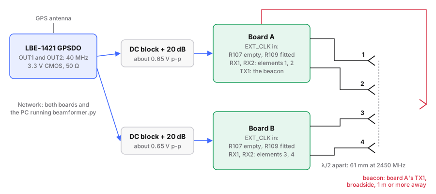
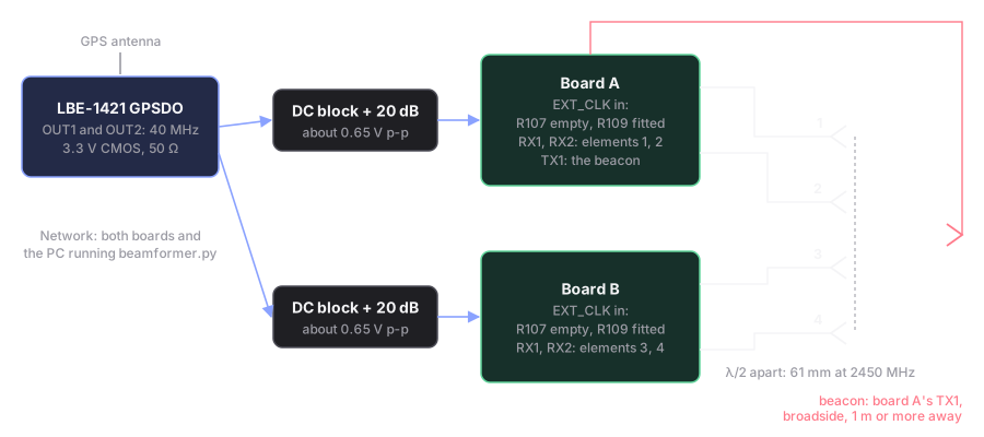
A receive beamformer, built on the automation server: two boards on one reference clock become a line of four antennas (A:RX1, A:RX2, B:RX1, B:RX2). A beacon plays on board A's TX1, the script calibrates the array with the beacon straight ahead, then steers a beam from −90° to +90° and reports where the beacon is.
The script is
tools/automation/examples/beamformer.py;
it runs on one board, two boards, or more.
Run on one board so far
On 2026-10-05 it ran on one board, two elements, with the direction emulated on the bench (step 1): its numbers below are measured. The two-board steps have not been run on hardware yet. They follow from the external reference page, and every number in them that was not measured says so.
Why one reference is not enough
A shared reference makes both boards' LOs and sample clocks run at exactly the same rate. It does not line them up:
| What | Across two boards | What the script does |
|---|---|---|
| LO frequency | equal, once both run from one reference; on their own crystals they differ by a few ppm (about 5 kHz at 2.45 GHz) | the lock check measures each element's offset from the beacon |
| LO phase | a new, unknown value at every retune, rate change and reboot | calibrates with the beacon straight ahead; recalibrate after any of those |
| When a capture starts | different on each board: two network calls start milliseconds apart, and this design has no shared start (no AD9361 multi-chip sync) | reads each element's phase at the matched filter's peak, which does not depend on where in the capture the peak falls |
Within one board, RX1 and RX2 share an LO, so their phase difference survives a retune: +149.5° and +149.8° in two runs that each configured the board afresh. Across boards it does not.
1. Try it on one board
No second board and no antennas: the bench loops TX1 → 20 dB → RX1 and TX2 → 30 dB → RX2. The beacon plays on both transmitters, and a phase step on TX2 stands in for a wave arriving from each angle.
# run from: the repo root on your PC, after looking at both transmit ports
./devkit tx-guard affirm 0
./devkit tx-guard affirm 1
# run from: tools/automation
.venv/bin/python examples/beamformer.py --emulate=-60,-30,0,30,60
# run from: the repo root on your PC
./devkit tx-guard revoke both
You should see, measured on 2026-10-05:
2 elements (RX1, RX2), 61.2 mm apart, LO 2450 MHz (wavelength 122.4 mm); beacon on board 1 TX1

Lock check, 5 snapshots, nothing moving:
   element     level    SNR    offset  coherence  phase spread
       RX1   -21.7 dBFS  65.3 dB    -0.0 Hz      1.000
       RX2   -31.3 dBFS  65.7 dB    -0.0 Hz      1.000       0.1 deg
calibrated at 0 degrees: RX1 +0.0 deg, RX2 +149.8 deg

Emulated directions (TX2's phase stands in for the angle):
     -60 deg: found  -60.1 deg (-0.1 from -60); beam SNR 65.4 dB, best single element 65.6 dB
     -30 deg: found  -30.0 deg (-0.0 from -30); beam SNR 65.2 dB, best single element 65.3 dB
      +0 deg: found   +0.1 deg (+0.1 from +0); beam SNR 65.5 dB, best single element 65.8 dB
     +30 deg: found  +30.1 deg (+0.1 from +30); beam SNR 65.3 dB, best single element 65.6 dB
     +60 deg: found  +59.7 deg (-0.3 from +60); beam SNR 65.1 dB, best single element 65.2 dB

mean SNR per element during the lock check: RX1 65.3 dB, RX2 65.7 dB
transmitters now: fishball.local TX1 -89.75 dB, TX2 -89.75 dB
It also writes beamformer.csv, beamformer-check.svg and
beamformer-emulate.svg where you run it:


What it shows, and what it does not:
- The direction is found within 0.3°. The calibration, the steering and the sign convention work end to end.
- The beam's nulls are shallow (−2 to −6 dB) because RX2's loop has 10 dB more attenuation: two unequal elements cannot cancel each other. Two elements also cannot tell a direction near −60° from one near +90° well.
- No array gain here. Two equal elements with independent noise gain 3 dB,
four gain 6 dB (
tests/test_beamformer.pychecks the 6 dB on synthetic data). On this bench, at −40 dB, both elements reached about 65 dB SNR although their levels differ by 9.6 dB: the floor is not thermal noise but something both elements share, most likely the shared LO's phase noise, which adding them cannot average out. With the beacon at −80 dB the SNRs followed the levels (41.7 and 31.5 dB), and the beam came within −0.4 to +0.8 dB of the stronger element, as equal-gain combining of two elements 10 dB apart predicts.
2. Put both boards on one reference
What you need: a second board on the Debian root, the LBE-1421 GPSDO with its GPS antenna, two DC blocks, two attenuators of about 20 dB, and SMA to U.FL leads.
- Move R107 to R109 on both boards, as on the external reference page. From then on a board does not start its radio unless the reference is running at boot.
- Set both GPSDO outputs to 40 MHz with Leo Bodnar's configuration tool.
At 40 MHz the device tree's
clock-frequencystays as it is. - Cable each output through a DC block and about 20 dB to one board's
EXT_CLK. The outputs are 3.3 V CMOS from 50 Ω;EXT_CLKtakes at most 1.3 V p-p, AC-coupled. About 0.65 V p-p through 20 dB is an open-circuit calculation, not a measurement with this GPSDO: check it on a scope. - Power the GPSDO first, and let it lock to GPS, then power both boards.
-
Give the second board its own name. With only that board on the network:
# run from: the repo root on your PC
./devkit net name fishball-b
Then check the two do not share a MAC address (networking).
-
Install the server on both.
# run from: the repo root on your PC
BOARD=fishball.local ./devkit automation install
BOARD=fishball-b.local ./devkit automation install
You should see: both boards boot with their radio up
(./devkit automation status on each). The lock check in step 3 is what shows
they share the reference.
3. Check the lock, cabled
Before any antenna: board A's TX1 → 20 dB → a four-way splitter → the four receivers, with four cables of equal length. 20 dB and the splitter's 6 dB keep each receiver below its +2.5 dBm limit even at the transmitter's full (estimated) +19 dBm.
# run from: the repo root on your PC, after looking at board A's TX1A
BOARD=fishball.local ./devkit tx-guard affirm 0
# run from: tools/automation
.venv/bin/python examples/beamformer.py --boards fishball.local,fishball-b.local --check 10
Press Enter at the first prompt (equal cables are "broadside"), then Enter
once more for a scan, then q.
You should see in the lock check, on all four elements: an offset near 0 Hz, coherence near 1.000, and a phase spread of a few degrees at most; the scan should find about 0°. That is what one board measured in step 1. On two boards it has not been run yet.
B:RX1 and B:RX2 say NOT LOCKED
Their phase rotates against the beacon within one capture: board B is not
on the GPSDO's reference. Check R107 and R109 on board B, the cable, and that
the GPSDO was running before the board booted. Two independent 40 MHz
crystals differ by a few ppm, about 5 kHz at 2.45 GHz; the script flags any
element whose coherence falls below 0.9, which a 300 Hz offset already does
(tests/test_beamformer.py).
4. Find a direction, over the air
Which antennas
Identical, broad-beam antennas, all facing the same way. The direction comes from the phase differences between them, not from the antennas: each one only sets where the array can see, because the array's pattern is the element's pattern multiplied by the array factor.
| Element | For this array |
|---|---|
| Patch, or a monopole with a reflector (60–90° beam) | the best fit: no front/back ambiguity, a few dB more per element, and a field of view of about ±60°, where a line array resolves well anyway |
| Omnidirectional (vertical whip, dipole, sleeve dipole) | works, and is the easiest start. A line of them cannot tell front from back: a beacon 30° in front looks the same as one 30° behind. Keep the beacon in front, or put a metal plate about a quarter wavelength behind the line (31 mm at 2450 MHz) |
| High gain (Yagi, horn) | no. They sit far wider than half a wavelength apart (61 mm at 2450 MHz, 173 mm at 868 MHz), and an array spaced wider than that has grating lobes: one beacon appears at two or more angles. Their narrow beam would also limit what the array can see |
- The same model, mounted the same way, on cables of equal length. The calibration removes cable and chain differences at one frequency, and assumes every element has the same pattern.
- The same polarisation as the beacon. Vertical on both is simplest.
- Expect some error that grows with angle. At half a wavelength the antennas couple to each other and change each other's patterns; calibrating at 0° corrects 0° exactly. How large the error gets at the edges has not been measured.
- The beacon antenna can be anything in the band, omnidirectional included, at least 1 m away.
A first test at 2450 MHz: four identical 2.4 GHz vertical whips or sleeve dipoles 61 mm apart, with a metal plate behind them to use the whole −90° to +90°.
Steps
- Four antennas in a line, 61 mm apart (half a wavelength at 2450 MHz), in array order: A:RX1, A:RX2, B:RX1, B:RX2, chosen as above. Their cables should be equal in length; the calibration absorbs any difference, but only at one frequency.
- The beacon antenna on board A's TX1, straight ahead of the middle of the line, at least 1 m away: the far field of a four-element, half-wavelength array starts at about 0.55 m. At −40 dB, the default, the beacon radiates about −21 dBm, from the estimated +19 dBm full scale; 2450 MHz is in the licence-free 2.4 GHz band.
-
Record the leak first, and remove it. Inside board A, TX1 leaks into its own receivers 48–60 dB down at 1–3 GHz (measured); free space between two antennas 1 m apart at 2.45 GHz is 40 dB, so the leak can be within about 10–20 dB of the signal on A's elements.
--leakrecords it with the beacon's antenna replaced by a 50 Ω load, and subtracts it from every snapshot.# run from: tools/automation .venv/bin/python examples/beamformer.py --boards fishball.local,fishball-b.local --leak --rx-gain 50 -
Follow the prompts: the load, the antenna back, the beacon straight ahead (calibration), then move the beacon and press Enter for each scan. Each scan prints the direction found and redraws
beamformer-scans.svg. Positive angles are towards element 4.
Receive gain: --rx-gain 50 is a starting point, not a measured setting; aim
for a level between about −40 and −15 dBFS in the lock check.
How it works
| Step | What the script does |
|---|---|
| Beacon | A chirp from −2 to +2 MHz, 67 µs long, every 0.53 ms (8192 samples at 15.36 MS/s), uploaded once |
| Snapshot | the beacon plays; every board records RX1 and RX2 at once (one thread per board); the beacon stops and mutes |
| Per element | a matched filter per beacon period; the complex value at the peak, averaged over the 16 periods. The sweep is symmetric about the LO, so that value's phase does not move with a fractional-sample shift either (tested: under 2° for half a sample, against 23° for a 0 to +4 MHz sweep) |
| Lock check | per element: the offset from the beacon (phase step between periods), the coherence (|mean| / mean|·| of the per-period peaks), and the spread of its phase relative to element 1 over the snapshots |
| Calibration | each element's phase relative to element 1 with the beacon at 0°, averaged as unit phasors. Phase only: a weaker element is not amplified |
| Beam | delay-and-sum: the calibrated elements weighted by the steering vector for each angle, every 0.1° from −90° to +90°; the strongest angle is the direction |
Change it
| To | Change |
|---|---|
| another band | --lo-mhz 868; the spacing follows (half a wavelength: 173 mm at 868 MHz) unless --spacing-mm sets it |
| more boards | --boards a.local,b.local,c.local: two elements per board, in that order, each board on the same reference |
| the beacon on another board or transmitter | --beacon 2:1 (board 2, TX1) |
| a quieter or louder beacon | --attenuation -60; louder than −10 dB is refused unless --pad states at least 20 |
Every call and rule underneath: the automation server.