Controlling the USER LED
The board's one programmable LED: how it is wired, what it shows by default, where a setting survives a reboot, and what to use for an LED driven by FPGA logic. To drive it or change its default, follow control the USER LED.
The board has three LEDs between the USB2.0 and DEBUG ports:
| LED | Driven by | Can you control it? |
|---|---|---|
PWR |
Power rail | No: hardwired |
DONE |
The FPGA's own configuration logic | No: it goes high when the bitstream loads |
USER |
Linux, through a PS GPIO pin | Yes: this page |
Drive it from Linux
A trigger is a kernel rule that drives an LED automatically; the LED is
/sys/class/leds/led0:green, with trigger, brightness, delay_on and
delay_off files. The commands: control the USER LED.
A script written on the board vanishes at reboot on Buildroot (firmware/,
a ramdisk) unless it is in /mnt/jffs2 or, better, in firmware/patches/. On
Debian (firmware-modern/) the root is ext4 and keeps it; run it at boot from
a systemd unit (/mnt/jffs2/autorun.sh is not run there), and commit it to
firmware-modern/debian/overlay/ so the next card has it.
How it is wired
// in firmware/src/linux/arch/arm/boot/dts/zynq-pluto-sdr-fishball.dts (excerpt)
leds {
    compatible = "gpio-leds";
    led0 {
        label = "led0:green";
        gpios = <0x09 0x00 0x00>;          /* controller, pin 0, active high */
        linux,default-trigger = "heartbeat";
    };
};
Phandle 0x09 is gpio@e000a000, the PS (processing system, the ARM side)
GPIO controller, so the LED is on MIO pin 0.
You cannot drive this LED from your HDL
MIO pins are not routed into the Programmable Logic; it does not appear in
system_top.v or system_constr.xdc. Driving it is a software job.
What it does by default here: it follows the transmitter
The factory firmware blinks a heartbeat. These builds instead select a kernel
trigger called tx-active at boot, from
S21misc on
Buildroot and fishball-identity (run by fishball-identity.service) on Debian.
Both check the trigger exists first, so a kernel without patch 0012 keeps the
heartbeat.
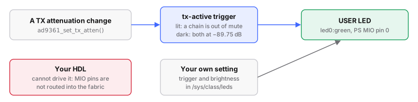
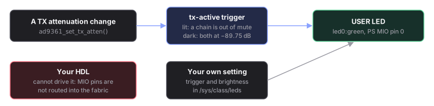
Lit whenever either transmit chain is out of full attenuation. Dark when both sit at the −89.75 dB mute floor.
It is driven from ad9361_set_tx_atten(), which every attenuation change passes
through; there is no polling. It follows the attenuator rather than the DMA
buffer because attenuation can be raised with no buffer open, while the LO (local
oscillator) leaks out of the SMA; a stream into a fully attenuated chain leaves
it dark.
| State | LED |
|---|---|
| both channels muted, no buffer | dark |
| TX1, TX2 or both raised, no buffer | lit |
| gain set, then a DMA stream running | lit |
| DMA stream running, both channels still muted | dark |
| stream ends, kernel re-mutes | dark |
To keep the heartbeat instead, set a U-Boot variable and reboot:
# run from: the board (Buildroot or Debian)
fw_setenv tx_led 0
Making your own setting the default at boot
Choose the trigger from userspace at boot, not by editing
linux,default-trigger in zynq-pluto-sdr-fishball.dts. On
firmware/ the device tree recompiles byte-for-byte
identical to the factory board's (provenance); on
firmware-modern/ a tree change needs a reflash,
and firmware-modern/verify_dtb.py (run in CI) asserts the tree still asks for
heartbeat.
The S21misc line, the systemd unit and the patch command:
control the USER LED.
If you want an LED your FPGA logic drives directly
Use a pin that reaches the PL (programmable logic, the FPGA fabric). The easiest
are the four 3.3 V header pins of the sample-locked GPIO feature: JP5 pins
7/9/11/13, balls V10/U9/U10/T9, bank 13, LVCMOS33
(tx-gpio-bitmap.md). With that feature off they are
ordinary Linux GPIOs (978–981 on the factory 5.15 kernel, 584–587 on
6.12), so an LED + resistor from a pin to GND (JP5 pin 2 or 20) needs no HDL:
drive it from /sys/class/gpio (GPIO). To drive one from fabric
logic, take the pin over in system_bd.tcl the way tx_gpio_bitmap does.
Any other header pin needs the board schematic first: driving a pin that is
an input or tied elsewhere can damage the board. Then constrain it, add
output my_led to system_top.v, drive it, and rebuild (a counter off
axi_ad9361/l_clk makes a good first test; see
Add your own HDL):
# in firmware/src/hdl/projects/pluto/system_constr.xdc
set_property -dict {PACKAGE_PIN <ball> IOSTANDARD LVCMOS33} [get_ports my_led]
To have the USER LED reflect PL state, expose it in an AXI register and have
a userspace loop copy it to brightness.